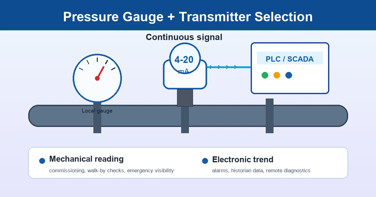
Pressure transmitter vs pressure gauge selection is a practical instrumentation decision: a mechanical gauge gives local visual pressure indication, while a pressure transmitter converts the process pressure into an electrical signal such as 4-20 mA, HART or digital output for PLC, SCADA or historian systems. In pumps, compressors, hydraulic systems, water treatment skids and process lines, the right answer is often not one device replacing the other, but a clear role for each instrument.
What a pressure transmitter proves, and what a pressure gauge still proves
Pressure transmitter vs pressure gauge selection starts with the measurement role, not with the product photo. A pressure transmitter is an electronic pressure instrument: the sensing element converts process pressure into an electrical signal, commonly 4-20 mA, HART, 0-10 V, RS-485 or a fieldbus output. A mechanical pressure gauge is a local indicating instrument: a Bourdon tube, diaphragm or capsule element moves a pointer across a dial without external power.
The transmitter is better when the pressure value must become data: alarms, shutdown logic, pump sequencing, trend records, leak detection, filter maintenance or remote diagnostics. The gauge is better when a technician needs immediate local confirmation during commissioning, isolation, line flushing, maintenance handover or a power and signal failure. The professional decision is rarely “which one is modern?” It is “which question does this instrument answer, and what happens if the reading is wrong?”
Review Mechanical Pressure Gauge Installation→Measurement principle: Bourdon tube, diaphragm element and electronic sensing cell
A Bourdon tube gauge uses an elastic curved tube that tends to straighten as internal pressure rises. Linkage and movement convert that small displacement into pointer rotation. It is robust, easy to read and suitable for many industrial ranges, but it has moving parts and can be affected by vibration, pulsation, overpressure and mechanical wear. A diaphragm pressure gauge uses a flexible membrane, often with a diaphragm seal when the medium is corrosive, viscous, crystallizing or sanitary. Capsule gauges are used for very low pressure or differential pressure indication.
A pressure transmitter normally uses a strain gauge, piezoresistive, capacitive or ceramic sensing cell. The sensor output is conditioned by electronics, temperature compensation and scaling. That makes it useful for continuous monitoring, but it introduces requirements that a mechanical gauge does not have: power supply, signal wiring, grounding, shielding, enclosure rating, electromagnetic compatibility, loop resistance and control-system scaling.
For process engineers, the practical point is this: a gauge failure is often visible as pointer jump, zero shift, fogging or a stuck movement; a transmitter failure may appear as a frozen value, noisy signal, wrong engineering unit, incorrect PLC scaling or a blocked impulse line that still sends a stable but false reading.
Pressure transmitter vs pressure gauge selection by application
For simple water, compressed-air or non-critical utility lines, a mechanical pressure gauge may be enough when operators only need periodic local checks. For automated equipment, batch processes, remote pump stations, data centers and safety-related process alarms, a pressure transmitter is normally required because the value must enter PLC, SCADA, BMS or historian software.
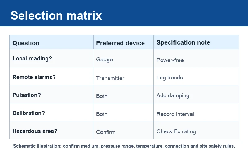
| Application question | Better starting point | Technical reason |
|---|---|---|
| Does an operator need a reading without power? | Mechanical pressure gauge | The dial remains visible during shutdown, lockout and manual venting. |
| Does the system need an alarm, shutdown or trend? | Pressure transmitter | The signal can be logged, compared and used by control logic. |
| Is the line vibrating or pulsating? | Gauge plus damping; transmitter with suitable response | Pulsation can damage movements and create noisy electronic signals. |
| Is the medium corrosive, viscous, crystallizing or sanitary? | Diaphragm seal with gauge or transmitter | Wetted material, fill fluid and cleanability become the main specification. |
| Is the area hazardous? | Confirm protection concept before powered devices | A transmitter may require Ex, intrinsic safety, barrier and wiring approval. |
For mechanical mounting details, see the pressure gauge installation best practices. For filters, strainers and membrane systems, compare the differential pressure gauge selection guide.
Request a Gauge and Transmitter Specification CheckOur engineers respond within 24 hours→Signal types, wiring limits and why 4-20 mA is still common
The most common transmitter output in industrial service is 4-20 mA. It is widely used because current signals tolerate cable length and voltage drop better than simple voltage signals. A live zero at 4 mA also helps distinguish a valid low reading from a broken loop, depending on the control system design. HART adds digital communication over the analog loop, so technicians can read device range, damping, diagnostics or tag data without replacing the 4-20 mA infrastructure. Voltage outputs such as 0-10 V are more common in short-distance equipment panels. RS-485, Modbus or fieldbus outputs appear in smart skids or integrated systems, but they require software and addressing discipline.
Signal selection is a specification issue, not a catalog preference. Buyers should define loop power, maximum load resistance, cable length, shield grounding, connector type, ingress protection and whether the signal should fail high, fail low or hold last value. In a pump protection loop, response time may matter. In a slow tank pressure application, damping may be useful. In hydraulic presses, a very fast signal can show pressure spikes, but it can also overload the control logic with noise if sampling and filtering are not planned.
Range, overpressure, accuracy and temperature effect must be read together
Gauge range and transmitter span are often selected too late. For mechanical gauges, a common engineering rule is to keep normal operating pressure away from the very bottom and very top of the dial; many specifications target the middle part of the scale for routine operation while leaving room for short pressure excursions. For transmitters, the calibrated span should match the useful process band, but the sensor must also survive maximum working pressure, proof pressure and possible overpressure events.
Accuracy wording must be read carefully. A mechanical dial gauge may specify accuracy as a percentage of full scale, while a transmitter may specify reference accuracy, total error band, temperature effect, long-term stability and repeatability. A transmitter with attractive reference accuracy can still produce a larger field error if ambient temperature changes, the range is turned down too far, the impulse line is poor, or the installation creates vibration and thermal stress.
Calibration requirements are separate from catalog accuracy. Define the calibration interval, acceptance tolerance, reference instrument uncertainty and whether a traceable or accredited certificate is required. For transmitters used in industrial-process control, IEC 60770-1 describes methods for evaluating transmitter performance with pneumatic or electric analogue outputs. For analog pressure gauges and attachments, ASME B40.100 is a relevant North American reference. For pressure traceability language, NIST pressure and vacuum calibration services are useful context. External references: IEC 60770-1, ASME B40.100, NIST pressure/vacuum calibrations.
Installation accessories: valves, snubbers, siphons, diaphragm seals and manifolds
Professional pressure instrument selection includes the accessories around the instrument. An isolation valve lets technicians remove or calibrate a gauge or transmitter without depressurizing the entire line. A bleed or vent point helps release trapped pressure before maintenance. A snubber or pulsation dampener can protect a gauge movement and reduce signal noise on reciprocating pumps, compressors and hydraulic systems. A siphon protects a pressure gauge from direct high-temperature steam by holding a condensate barrier, but it must be installed and filled correctly.
A diaphragm seal separates the instrument from the process medium. It is useful for corrosive chemicals, viscous liquids, crystallizing media, food and pharmaceutical service, wastewater slurry or any medium that should not enter a Bourdon tube or transmitter port. The seal adds its own specification variables: diaphragm material, process connection, fill fluid, capillary length, ambient temperature, response time and vacuum suitability.
For differential pressure applications, use a proper manifold, equalizing valve and safe vent procedure. A pair of independent pressure gauges can show two local readings, but a true differential pressure instrument gives the pressure drop directly and reduces reading mistakes when filter loading or membrane fouling is the maintenance variable.
Failure diagnosis: how to compare the local gauge and transmitter reading
A gauge and transmitter pair is valuable because disagreement is diagnostic. If the transmitter alarm is high but the local gauge is normal, check PLC scaling, transmitter zero, range configuration, impulse line blockage, frozen line, closed isolation valve and wiring noise. If the gauge is high but the transmitter is normal, check whether the two instruments share the same tapping point, whether one valve is closed, whether the gauge pointer is bent, or whether the gauge has been damaged by overpressure.
If both readings are unstable, look for real process pulsation, pump cavitation, regulator hunting, compressor cycling, gas pockets in liquid lines or liquid hammer. If both readings drift slowly, check temperature change, process fouling, trapped air, diaphragm seal fill issues, clogged snubber or calibration drift. In hydraulic systems, short pressure spikes can damage a gauge even when average pressure looks acceptable; the specification may need a restrictor, liquid-filled gauge, digital peak capture or transmitter with suitable overpressure rating.
What pressure transmitter vs pressure gauge selection cannot prove
Pressure instruments improve visibility, but they do not prove that a process is safe by themselves. They do not replace relief valves, pressure testing, shutdown interlocks, hazardous-area classification, sanitary validation, SIL analysis, operator procedure or engineering approval. A transmitter can report a stable but false value if the impulse line is blocked. A gauge can look normal while the process connection is isolated. A diaphragm seal can protect the instrument but slow the response if the capillary and fill fluid are poorly chosen.
For high-pressure, high-temperature, corrosive, oxygen, ammonia, hydrogen, food-grade or explosive-atmosphere service, confirm wetted materials, seal fluid, pressure range, cleaning requirement, electrical protection and documentation against the actual site conditions. Manogauge can support Zhejiang-manufactured ISO 9001 pressure gauge selection and related instrument discussions, but final suitability must be approved by the project engineer, plant safety owner or process licensor.
Practical RFQ checklist for combined gauge and transmitter packages
A useful RFQ should make the process conditions visible before the supplier quotes. Include service medium, normal pressure, maximum pressure, vacuum possibility, pressure cycles, process temperature, ambient temperature, vibration, pulsation, mounting position, connection thread, wetted material, case material, ingress protection, output signal, power supply, cable entry, dial unit, accuracy requirement, calibration document, tagging, packing and destination market.
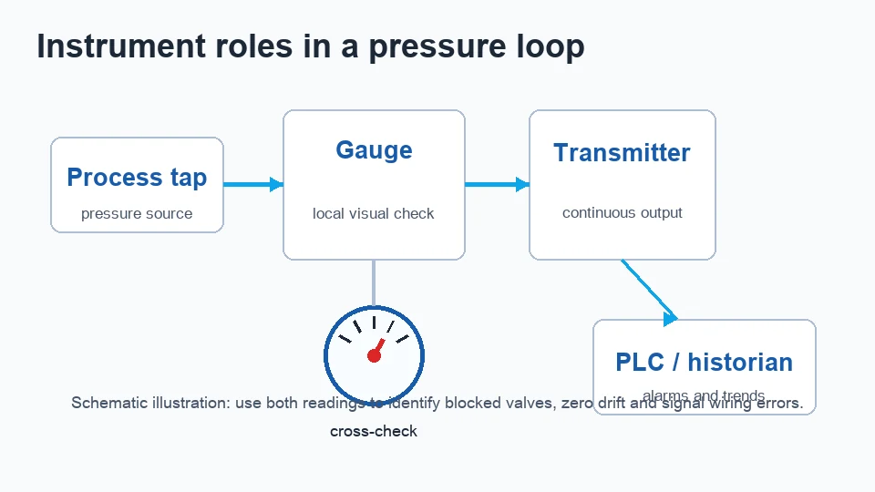
For a combined gauge and transmitter package, also define whether both instruments share the same tapping point, whether isolation valves are included, whether a manifold is required, whether the transmitter is used for control or monitoring only, and what reading difference is acceptable during commissioning. In pressure transmitter vs pressure gauge selection, the professional result is a documented measurement chain: process tap, isolation, protection accessory, sensing element, local indication, electronic signal, calibration record and maintenance procedure.
Key takeaways
- A mechanical pressure gauge and a pressure transmitter prove different things: local process visibility versus electronic process data.
- Professional selection must include sensing principle, signal output, range, overpressure, temperature effect, calibration document and installation accessories.
- Accessories such as isolation valves, snubbers, siphons, diaphragm seals and manifolds often decide whether the instrument survives the real process.
- A paired gauge and transmitter can be used diagnostically: disagreement points to scaling, blocked impulse lines, valve position, overpressure damage or true process instability.
- Pressure transmitter vs pressure gauge selection improves visibility but does not replace relief protection, validation, hazardous-area review or engineering approval.
Frequently asked questions
What is the main technical difference between a pressure transmitter and a pressure gauge?
A pressure gauge gives local visual indication through a mechanical sensing element such as a Bourdon tube or diaphragm. A pressure transmitter converts pressure into an electronic signal such as 4-20 mA, HART or digital output for a control system.
When should both a gauge and a transmitter be installed on the same line?
Use both when operators need local confirmation and the control system also needs alarms, trends or interlocks. Pump discharge, compressor receivers, hydraulic skids, boiler auxiliaries and remote water systems commonly benefit from both readings.
How should range be selected for a gauge and a transmitter?
Define normal pressure, maximum working pressure, possible overpressure and pressure cycles. A gauge should not run permanently at the extreme ends of the dial; a transmitter span should match the useful process band while the sensor overpressure rating protects it from abnormal events.
Why can a 4-20 mA transmitter and a gauge disagree?
Common causes include PLC scaling error, transmitter zero drift, blocked or frozen impulse line, closed isolation valve, different tapping points, gauge pointer damage, clogged snubber or real pressure pulsation.
Which accessories should be specified with pressure instruments?
Specify isolation valves, bleed or vent points, snubbers for pulsation, siphons for steam, diaphragm seals for corrosive or sanitary media, and manifolds for differential pressure service when the process requires them.
Can pressure instruments replace safety devices?
No. They support visibility and control, but they do not replace relief valves, pressure testing, interlocks, hazardous-area review, sanitary validation or engineering approval.