
Proper pressure gauge installation is critical for accurate readings, extended service life, and maintaining warranty validity. Incorrect installation can lead to premature failure, inaccurate measurements, and safety hazards. This guide provides essential best practices for Manogauge industrial pressure gauges, covering everything from mounting orientation and thermal protection to pulsation dampening and proper connection techniques. Adhering to these guidelines, which align with standards like EN 837-1 and ASME B40.100, ensures optimal performance and reliability in demanding industrial environments. Understanding these nuances is vital for B2B distributors, OEM equipment makers, and plant engineers seeking to maximize instrumentation uptime and data integrity.
1. Mounting Position and Orientation
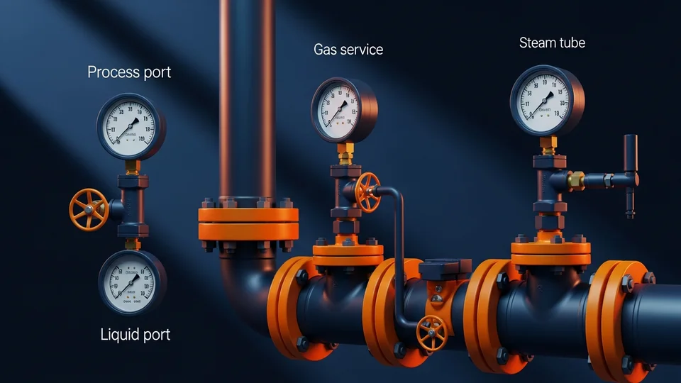
The mounting position of a Bourdon-tube pressure gauge significantly impacts its accuracy and longevity. For most applications, the gauge should be mounted vertically with the process connection pointing downwards. This orientation allows any condensate or process fluid to drain away from the Bourdon tube, preventing accumulation that could lead to measurement errors or corrosion. It also ensures the internal mechanism operates under its designed gravitational load, minimizing stress on pivots and linkages.
When vertical mounting is not feasible, such as on horizontal lines, a remote mounting solution using an impulse line is recommended. If direct horizontal mounting is unavoidable, ensure the gauge is positioned to prevent liquid traps within the Bourdon tube. For applications involving gases, the orientation is less critical, but a downward connection is still preferred to prevent particulate matter from settling inside the Bourdon tube.
Ambient temperature swings can also affect gauge accuracy. Per EN 837-1, a deviation from the reference temperature (typically 20°C) can introduce errors. For every 10°C change, expect an approximate 0.4% error of the full scale range. Therefore, avoid direct sunlight or proximity to heat sources. If extreme temperature variations are unavoidable, consider gauges with temperature compensation or remote mounting in a controlled environment. Always ensure the gauge dial is easily visible for routine inspection and readings, maintaining a comfortable viewing angle and adequate lighting.
Thread sealing and port selection are detailed in the NPT, BSP and metric thread connection guide.
Browse Our Pressure Gauge Catalog →Explore 143+ industrial gauge models→2. Steam Service: When to Use a Siphon Tube
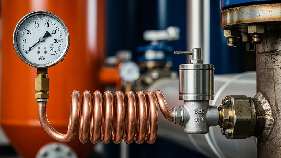
For steam service or any application where the process fluid temperature exceeds 60°C (140°F), a siphon tube (also known as a pigtail or coil siphon) is mandatory. The primary function of a siphon tube is to protect the Bourdon tube and internal components of the pressure gauge from direct exposure to high-temperature process fluid. Without a siphon, the extreme heat would rapidly degrade the gauge's sensitive metallic components, leading to material fatigue, calibration drift, and premature failure.
The siphon tube works by creating a condensate barrier or a heat dissipation zone. As steam enters the siphon, it condenses within the coiled section, forming a liquid seal. This condensate then transmits the process pressure to the gauge while preventing the hot steam from reaching it directly. The extended surface area of the siphon also facilitates heat transfer to the ambient air, further cooling the fluid before it reaches the gauge.
Before commissioning, the siphon tube must be filled with water (or a suitable non-freezing liquid for cold environments) to establish this protective barrier. This pre-filling is crucial to ensure immediate protection upon system startup. Manogauge recommends using stainless steel siphons for steam applications due to their superior corrosion resistance and high-temperature integrity. Always verify the siphon material compatibility with the process fluid and operating conditions to prevent chemical attack or stress corrosion cracking.
Steam and special-service layouts should be checked against EN 837-3 pressure gauge safety requirements.
For steam boiler-specific siphon sizing, gauge range selection, and valve type, see the steam boiler pressure gauge and siphon selection guide.
3. Pulsation Protection: Snubbers and Needle Valves
Pulsating pressures, common in pump discharge lines, compressor outlets, and hydraulic systems, are a leading cause of premature pressure gauge failure. These rapid pressure fluctuations cause excessive wear on the Bourdon tube, movement gears, and pointer, leading to pointer flutter, reduced accuracy, and ultimately, mechanical fatigue. To mitigate this, pulsation dampeners are essential.
Two primary devices are used for pulsation protection: snubbers and needle valves. A snubber is a passive device designed to absorb or restrict pressure surges. It typically contains a porous element (e.g., sintered metal, restrictor plug) or a small orifice that dampens the pressure fluctuations before they reach the gauge. Snubbers are available in various materials and orifice sizes to match specific process fluids and pulsation frequencies. For viscous fluids, a piston-type snubber might be more appropriate.
A needle valve provides adjustable dampening. By partially closing the valve, the flow of process fluid to the gauge is restricted, effectively smoothing out pressure pulsations. This offers greater flexibility in tuning the dampening effect to the specific application. However, it requires careful adjustment during commissioning to achieve optimal dampening without introducing excessive response lag. Both snubbers and needle valves also serve to protect the gauge from sudden pressure spikes during system startup or shutdown. Always ensure the dampening device is installed directly upstream of the pressure gauge for maximum effectiveness.
For pulsating service, compare dry vs. liquid-filled pressure gauges and the instrument data approach in ISA-S20 specification forms.
Request a Free QuoteOur engineers respond within 24 hours→4. Process Connection: Thread Sealing and Torque
Proper process connection is paramount for leak-free operation and accurate pressure transmission. The most common connection types are NPT (National Pipe Taper) and G (BSPP - British Standard Parallel Pipe) threads. For NPT connections, a thread sealant such as PTFE tape or pipe dope is required. Apply sealant only to the male threads, leaving the first two threads bare to prevent sealant particles from entering the process line and potentially fouling the gauge or system components. For G connections, a sealing washer (e.g., copper, PTFE, or bonded seal) is used, which seals on the face of the connection rather than the threads.
Torque values are critical to prevent leaks and avoid damaging the gauge or connection. Over-tightening can deform the gauge's internal mechanism, leading to calibration errors or even cracking the gauge casing. Under-tightening will result in leaks. While specific torque values vary by thread size and material, a general guideline for NPT connections is to hand-tighten, then use a wrench for an additional 1 to 2 turns. Always refer to the manufacturer's recommendations or relevant standards like ASME B40.100 for precise torque specifications. For G connections, tighten until the sealing washer is compressed, ensuring a firm, leak-tight seal without excessive force.
When installing, always use a backup wrench on the process connection fitting to prevent twisting the gauge casing or the process piping. Never use the gauge casing itself as leverage. Ensure the gauge is oriented correctly before final tightening. For differential pressure (DP) gauges, impulse lines should be of equal length and filled with the same fluid to ensure accurate pressure transmission and minimize errors due to hydrostatic head differences.
Acceptance readings should be matched to the pressure gauge accuracy class selection guide.
5. Commissioning, Maintenance, and EN 837-3 Service Criteria
Upon initial commissioning, slowly introduce pressure to the gauge to prevent sudden surges that could damage the Bourdon tube. Observe the pointer movement for smoothness and ensure it returns to zero when pressure is relieved. Verify that the gauge reading aligns with a known reference or another calibrated instrument. For gauges with an adjustable pointer, make any necessary zero adjustments before placing the system into full operation. Always ensure isolating root valves and three-valve manifolds are operated correctly to prevent over-pressurization or damage during startup and shutdown.
Routine maintenance includes periodic visual inspection for signs of damage, corrosion, or leaks. Check for pointer flutter, which indicates pulsation issues, and ensure the dial is clean and legible. Recalibration should be performed according to plant standards, typically annually, or if accuracy is suspected to be compromised. For gauges in critical service, more frequent checks may be warranted. Replace any gauge showing signs of significant damage or persistent inaccuracy.
EN 837-3 outlines specific criteria for pressure gauge service and replacement. Key indicators for replacement include: pointer not returning to zero, excessive pointer flutter, visible damage to the casing or window, internal corrosion, or consistent readings outside the specified accuracy class. Adhering to these criteria ensures continued reliability and safety. Manogauge gauges are designed for robust industrial service, but proper installation and maintenance are key to achieving their full operational lifespan and maintaining warranty validity.
If symptoms remain after installation correction, use the pressure gauge failure troubleshooting guide.
Key takeaways
- Mount gauges vertically with process port down to prevent fluid accumulation and ensure proper drainage.
- Always use a pre-filled siphon tube for steam service or process temperatures exceeding 60°C to protect the gauge.
- Install snubbers or needle valves directly upstream of the gauge to dampen pulsations from pumps and compressors.
- Apply thread sealant correctly (PTFE tape for NPT, washer for G) and use a backup wrench to achieve proper torque without damaging the gauge.
- Slowly introduce pressure during commissioning and adhere to EN 837-3 criteria for routine maintenance and timely replacement.
Related products
- Liquid-Filled Pressure Gauge - Radial (ZX-06-R) — 0–60 MPa
- Shock-Resistant Pressure Gauge - Radial (ZX-03-R) — 0–270 psi
Frequently asked questions
Why is a siphon tube necessary for steam applications?
A siphon tube protects the pressure gauge from high-temperature steam (>60°C) by creating a condensate barrier. This prevents direct heat exposure, which would otherwise degrade the Bourdon tube and internal components, leading to premature failure and inaccurate readings.
What is the correct torque for NPT pressure gauge connections?
For NPT connections, hand-tighten the gauge, then use a wrench for an additional 1 to 2 turns. Always use a backup wrench on the process connection fitting. Refer to ASME B40.100 or manufacturer specifications for precise torque values to avoid over-tightening.
How do ambient temperature swings affect pressure gauge accuracy?
Ambient temperature changes can cause thermal expansion or contraction of the Bourdon tube, leading to reading errors. Per EN 837-1, a 10°C deviation from the reference temperature (20°C) can introduce approximately 0.4% error of the full scale range. Avoid direct sunlight or heat sources.
When should I use a pulsation snubber vs. a needle valve?
A snubber provides passive, fixed dampening and is ideal for consistent pulsation. A needle valve offers adjustable dampening, allowing fine-tuning for varying pulsation frequencies or process conditions. Both protect the gauge from wear in pump/compressor lines.
What are common mistakes that void a pressure gauge warranty?
Common mistakes include: over-pressurization, improper installation (e.g., no siphon for steam), over-tightening connections, using incompatible process fluids, physical damage due to mishandling, and failure to use pulsation dampeners in high-pulsation environments.